

- Products
-

 Networking
- > AI Smart Managed Series
- > Industrial Ethernet
- Industrial PoE Media Converter
- Industrial Media Converter
- Industrial Unmanaged PoE Switch
- Industrial Managed PoE Switch
- Industrial Unmanaged Ethernet Switch
- Industrial Managed Ethernet Switch
- Industrial Serial Fiber Converter
- Industrial PoE Injector
- Industrial PoE Splitter
- Industrial PoE Extender
- Industrial Optical Switch
- Industrial PD Switch
- DIN-Rail Power Supply
- Rackmount DIN-Rail Bracket
- LED Screen Fiber Converter
- Industrial Ethernet Switch & 5G Router
- Industrial EOC Converter
- > Commercial Ethernet
-
 Video Transmission
-
 SFP Transceiver
-
 Other Fiber Optic & Networking Products
-
- Solutions
- News
- About
- Contact


 Networking
Industrial PoE Media Converter
Industrial Media Converter
Industrial Unmanaged PoE Switch
Industrial Managed PoE Switch
Industrial Unmanaged Ethernet Switch
Industrial Managed Ethernet Switch
Industrial Serial Fiber Converter
Industrial PoE Injector
Industrial PoE Splitter
Industrial PoE Extender
Industrial Optical Switch
Industrial PD Switch
DIN-Rail Power Supply
Rackmount DIN-Rail Bracket
LED Screen Fiber Converter
Industrial Ethernet Switch & 5G Router
Industrial EOC Converter
Video Transmission
1080P AHD CVI TVI over Fiber Converter
5MP AHD CVI TVI over Fiber Converter
Video Converter Rack
Multi-functional Video over Fiber Converter
AHD/CVI/TVI Video Multiplexer
SFP TransceiverOther Fiber Optic & Networking Products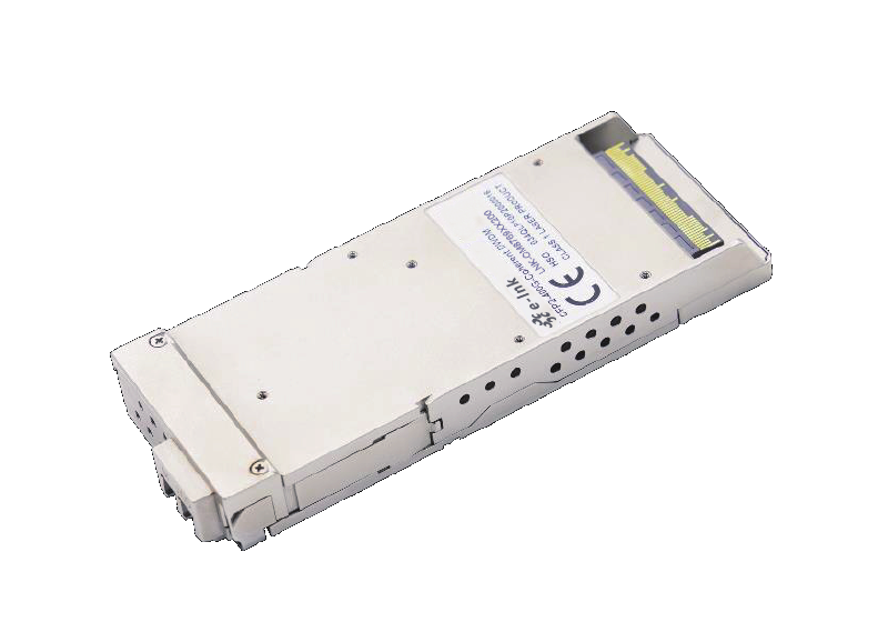
Huawei HiSilicon E-link 400G 640 km & 200G 2000 km CFP2 ( LNK-OM8769XX200 )
Model:LNK-OM8769XX200


The module is intended to be used on the host board of system integrators to support transmission over
DWDM links in Metro networks. As shown in Figure 1-1, it comprises high-data lanes, a single reference
clock from hosts, a single 3.3 V power supply, an MDIO interface, and dedicated alarm and control pins.
The LNK-OM8769XX200 module uses a 104-pin CFP2 MSA connector for all electrical interfaces with the
host board, whereas the optical interfaces on the line side are provided through the optical receptacles
on the CFP2. The module can be portioned into three functional parts: Tx path, Rx path and control &
power block.
All control interface pins are routed to the MCU and oDSP. The MCU is also used for fast control inside
the module such as modulator bias adjustment, firmware management, overall control coordination and
status reporting.
● Transmission reach beyond 640 km@400G and
2000 km@200G over SMF
● Hot-pluggable 104-pin electrical interface
● Supports 75 GHz/100 GHz channel spacing
● Supports OTN Framer
● Supports PM-16QAM (400G)/PM-QPSK (200G)
modulation
● Compliant with CFP2 MSA Hardware
Specification Rev. 1.0
● Compliant with CFP MSA Management Interface
Specification Version 2.6 (R06a)
● LC duplex connector
● Single 3.3 V power supply
● Typical power consumption: 32 W
● Operating case temperature: 0°C to 75°C
● DCI/Metro/Long-haul DWDM
640 – 2000 km
640 – 2000 km
The CFP2 module is designed to be inserted into a host board with a railing system that includes a heat
sink. The module is 107.5 mm x 41.5 mm x 12.4 mm in size and is mechanically compliant with the
requirements detailed in the CFP2 HW Baseline Design Rev.1L.
The optical port connections on the front of CFP2 are shown in the Figure 8-1. The CFP2 module will
support LC receptacles for standard single mode fiber. As mention in the OIF-CFP2-DCO-01.0, the
position of the optical connector in the Y and Z axes shall be specified by the CFP2-DCO module
manufacturer. In addition to the centered duplex LC connector location specified by the CFP MSA, the
CFP2-DCO IA also optionally allows the optical port position on the front of the module to be either left or
right-justified if needed to enable a certain vendor-specific implementation technology.
Please check whether the cage matches before using the module because of the side has dissipation
hole structure. For example, the cage part CN121C-104-0029(H1) (YAMAICHI) has side openings
and a side without sharp protrusions.
- Download FileName:E-link 400G 640km & 200G 2000km CFP2 (LNK-OM8769XX200) Datasheet Rev1.0.pdf Size: 2.86MB
| Part Number | Description |
| LNK-OM8769XX200 | 400G/200G, PM-16QAM/PM-QPSK, Coherent CFP2 |
Recommended Products